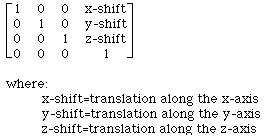
where:
The rigid body model requires that the real world Euclidean distance between any two coordinate locations to remain unchanged by the transformation. Since the AIR package allows anisotropic voxels sizes within a given file as well as different voxel sizes between files, these factors must be taken into account when applying a rigid body transformation. In the AIR package, the rigid body model is parameterized in terms of rotations around and translations along each of the three major coordinate axes. In order to make these parameters more inituitive, the rotations of the rigid body transformation are defined as taking place around the centers of the files rather than the origin of the internal coordinate system (located at one corner of the file).
The rigid body transformation for converting from an internal coordinate in the standard file to the corresponding internal coordinate in the reslice file is best expressed as the product of a series of homogenous transformation matrices:
(reslice file internal coordinates)=Zr*Cr*T*R*P*Cs*Zs*(standard file internal coordinates)
Zs=

where:
sxoom=(standard file voxel x size) / (smallest standard file voxel size)
syoom=(standard file voxel y size) / (smallest standard file voxel size)
szoom=(standard file voxel z size) / (smallest standard file voxel size)
smallest standard file voxel size=min(standard file voxel x, y and z sizes)
This homogenous transformation matrix remaps coordinate locations in the standard file to new coordinates with cubic voxels. The origin remains at (0,0,0).
Cs=

where:
sx_dim=standard file x-dimension
sy_dim=standard file y-dimension
sz_dim=standard file z-dimension
sxoom=(standard file voxel x size) / (smallest standard file voxel size)
syoom=(standard file voxel y size) / (smallest standard file voxel size)
szoom=(standard file voxel z size) / (smallest standard file voxel size)
smallest standard file voxel size=min(standard file voxel x, y and z sizes)
This homogenous coordinate transformation matrix shifts the origin from (0,0,0) to the exact center of the standard file.
P=
![]()
where:
ssize=min(standard file voxel x, y and z sizes)
rsize=min(reslice file voxel x, y and z sizes)
Coordinate units are modified by this homogenous coordinate transformation matrix to be equivalent to those used in an interpolated version of the reslice file.
R=

This homogenous coordinate transformation matrix performs rotations while preserving Euclidean distances between coordinate locations.
T=

This homogenous coordinate transformation matrix performs translations while preserving Euclidean distances between coordinate locations.
Note that the shifts have units of interpolated reslice file voxels
Cr=

where:
rx_dim=reslice file x-dimension
ry_dim=reslice file y-dimension
rz_dim=reslice file z-dimension
rxoom=(reslice file voxel x size) / (smallest reslice file voxel size)
ryoom=(reslice file voxel y size) / (smallest reslice file voxel size)
rzoom=(reslice file voxel z size) / (smallest reslice file voxel size)
smallest reslice file voxel size=min(reslice file voxel x, y and z sizes)
The origin of the coordinate system is shifted from the center of the file to internal coordinate (0,0,0) of the reslice file by this homogenous coordinate transformation matrix.
Zr=

where:
rxoom=(reslice file voxel x size) / (smallest reslice file voxel size)
ryoom=(reslice file voxel y size) / (smallest reslice file voxel size)
rzoom=(reslice file voxel z size) / (smallest reslice file voxel size)
smallest reslice file voxel size=min(reslice file voxel x, y and z sizes)
Cubic voxel coordinate locations are remapped to the actual voxel locations in the reslice file by this homogenous coordinate transformation matrix. The origin (0,0,0) remains unchanged.
Since the standard file interpolation matrix Zs is already implicit in the definition of the.air file transformation matrix, it is omitted from the matrix defined above when creating the .air file matrix: Zr*Cr*T*R*P*Cs.
Initialization files for the rigid body model consist of the following in ASCII format:
The reslice file voxel units referred to above are cubic (i.e., already interpolated to correct for reslice file voxel size anisotropy).
If no initialization file is specified, the default initialization for programs using a rigid body model is:
This results in the exact centers of the two files being aligned to one another.
There are many different ways to define a rigid body transformation. Without explicit equations such as those provided above, the terms pitch, roll, yaw, x-shift, y-shift, and z-shift are ambiguous. Other packages for registering or displaying images may not apply the transformations in the same order as the AIR package, so simple substitution of nominal parameters called "pitch","roll", etc. from other packages may not produce the desired result. In moving from standard file coordinates to reslice file coordinates, the AIR package performs rotations around the z-axis (yaw), x-axis (pitch), and y-axis (roll) in that order followed by translations x-shift, y-shift, and z-shift. Rotations operate around the exact centers of the files (before and after interpolation) and the sign conventions for both rotations and translations are arbitrary and may differ from those used in your alternative package. Shifts are defined in a version of reslice file space that has been interpolated to cubic voxels and are expressed in units of cubified voxels.
If your alternative package generates a linear algebraic transformation matrix of its own, don't forget that transformation matrices are dependent upon the coordinate system used and that the AIR internal coordinate system used to define transformation matrices may differ from that of your alternative package.
 Modified: December 16, 2001